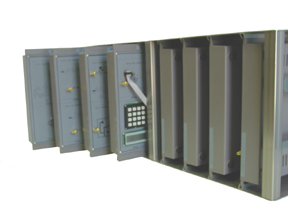
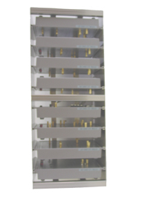
The Radio Frequency Lab comes with 8 different experiments, all conveniently stored in a metal case (pictured above) that can be sat upright or sideways. (Above Left - Upright View, Above Right - Side View)
WCL-10101
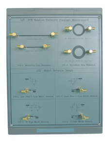
* PCB Relative Dielectric Constant Measurement
Experiment 1: Microstrip Line Resonator
(operation frequency: 1000 ~ 2000 MHz)
Experiment 2: Microstrip Ring Resonator
(operation frequency: 2000 MHz)
* Match Network Design
Experiment 1: L-type Match Network
(operation frequency: 900 MHz)
Experiment 2: Pi-type Match Network
(operation frequency: 900 MHz)
Experiment 3: T-type Match Network
(operation frequency: 900 MHz)
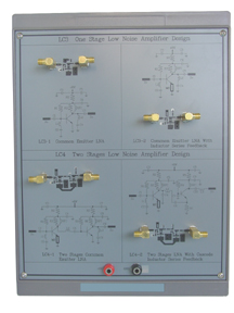
* One-Stage Low Noise Amplifier Design
Experiment 1: Measurement of Frequency Response.
(operation frequency: 890 ~ 915 MHz)
Experiment 2: Measurement of Noise Figure
(operation frequency: 890 ~ 915 MHz, Noise Figure: 2 dB)
Experiment 3: Measurement of 1 dB Compression Point
(operation frequency: 890 ~ 915 MHz, P1dB: -10m dB)
* Two-Stage Low Noise Amplifier Design
Experiment 1: Measurement of Frequency Response.
(operation frequency: 890 ~ 915 MHz)
Experiment 2: Measurement of Noise Figure
(operation frequency: 890 ~ 915 MHz, Noise Figure: 2 dB)
Experiment 3: Measurement of 1 dB Compression Point
(operation frequency: 890 ~ 915 MHz, P1dB: -13m dB ~ -18 dBm)
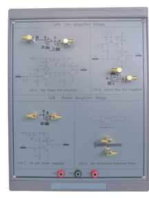
WCL-10103
* Preamplifier Design
Experiment 1: Measurement of Frequency Response.
(operation frequency: 800 ~ 1000MHz)
Experiment 2: Measurement of Noise Figure
(operation frequency: 800 ~ 1000MHz, Noise Figure: 3dB)
Experiment 3: Measurement of 1 dB Compression Point
(operation frequency: 890 ~ 915 MHz, P1dB: -13m dB ~ -18 dBm)
* Power Amplifier Design
Experiment 1: Measurement of Gain Flatness.
(operation frequency: 700 ~ 1000MHz, Gain Flatness: +/-2.5 dB)
Experiment 2: Measurement of 1 dB Compression Point
(operation frequency: 700 ~ 1000 MHz, P1dB: 15 dBm)
Experiment 3: Measurement of OIP3
(operation frequency: 915 MHz; IP3: 25 dBm)
Experiment 4: Measurement of Harmonics
(operation frequency: 915 MHz)
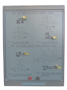
* Colpitts and Hartley Oscillator Design
Experiment 1: Measurement of Frequency & Output Power
(oscillation frequency: 800 ~ 900MHz)
Experiment 2: Measurement of Phase Noise
(Phase Noise: -90 ~ -110 dBc/Hz)
Experiment 3: Measurement of Gain Factor & Variable Bandwidth
(Gain Factor: 10 ~ 14 MHz/V; Variable Bandwidth: 50 ~ 70 MHz)
* Common Collector Colpitts Oscillator Design
Experiment 1: Measurement of Frequency & Output Power
(oscillation frequency: 750 ~ 850MHz)
Experiment 2: Measurement of Phase Noise
(Phase Noise: -90 ~ -110 dBc/Hz)
Experiment 3: Measurement of Gain Factor & Variable Bandwidth
(Gain Factor: 8~ 10 MHz/V; Variable Bandwidth: 40 ~ 50 MHz)
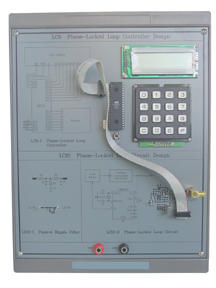
WCL-10105
* Phased-Locked Loop Controller Design
Experiment 1: LCD and Keypad Testing
(Locked Frequency Display; Locked Status Detection)
Experiment 2: MB15E03L Control Signal Testing
(Locked Frequency: 812 MHz; 825 MHz; 850 MHz)
* Phased-Locked Loop Circuit Design
Experiment 1: Measurement of Frequency Response for Loop Filter
(-3dB Frequency: 600 Hz)
Experiment 2: Measurement of Phase-Locked Loop
(Locked Frequency: 812 MHz; 825 MHz; 850 MHz)
Experiment 3: Measurement of FM Signal
(Audio Signal: 1KHz; Modulation Bandwidth: 100 ~ 150 KHz)
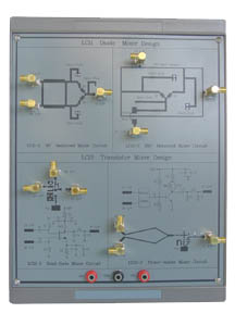
* Diode Mixer Design
Experiment 1: Measurement of Conversion Gain
(Radio Signal: 795 ~ 895 MHz or 1800 ~ 1900 MHz;
Local Signal: 915 MHz ~ 1780 MHz; Intermediate Signal: 20 ~ 100 MHz)
Experiment 2: Measurement of 1 dB Compression Point
(Radio Signal: 845 ~ 1850 MHz
Local Signal: 915 MHz ~ 1780 MHz; Intermediate Signal: 70 MHz)
Experiment 3: Measurement of Isolation
(Local Signal: 840MHz ~ 990 MHz or 1705 ~ 1855 MHz)
* Transistor Mixer Design
Experiment 1: Measurement of Conversion Gain
(Radio Signal: 877 ~ 977 MHz or 910 ~ 1010 MHz; Local Signal: 857 MHz ~ 850 MHz; Intermediate Signal: 20 ~ 100 MHz or 60 ~ 160 MHz)
Experiment 2: Measurement of 1 dB Compression Point
(Radio Signal: 927MHz or 910 MHz; Local Signal: 857 MHz or 850 MHz; Intermediate Signal: 70 MHz 0r 60 MHz)
Experiment 3: Measurement of Isolation
(Local Signal: 782MHz ~ 932 MHz or 840 ~ 990 MHz)
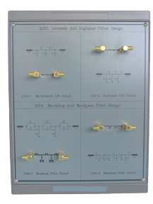
* Low-Pass and High-Pass Filter Design
Experiment 1: Measurement of Frequency Response.
(operation frequency: 500 ~ 1500 MHz; Low-pass -3dB frequency: 900 MHz
High-pass -3dB Frequency: 900 M Hz)
* Band-Stop and Band-Pass Filter Design
Experiment 1: Measurement of Frequency Response.
(operation frequency: 500 ~ 1500 MHz; Band-stop center Freq.: 900 MHz
Bandwidth: 200 MHz; Band-pass center Freq.: 70 MHz, Bandwidth: 20 MHz)
WCL-10108
* IF FM Demodulation Circuit
Experiment 1: Measurement of IF FM Demodulation Circuit
(intermediate Signal: 70.7 MHz, Modulation Bandwidth: 20 KHz)
* Audio Signal Processing Circuit
Experiment 1: Measurement of Pre-emphasis and Compression for Audio Signal
(Audio Signal: 20 Hz ~ 50 KHz)
Experiment 1: Measurement of De-emphasis and Decompression for Audio Signal
(Audio Signal: 20 Hz ~ 50 KHz)
Optional Equipments
FG-442002: Function Generator and DC Power Supply
Function Generator:
Two signal output ports
Freq. Range: 10 Hz ~ 100KHz and 100Hz ~ 1 MHz
Waveforms: Sine, Triangle, Square, TTL Pulse
Amplitude: 10 Vpp
Built-in 6-digit frequency counter
Large 0.5" LED display
Overload protection
DC Power Supply:
Triple bipolar voltage output
Constant voltage operation
Low ripple and noise
RG-442003: 3-band Signal Generator
Five signal output ports
Frequency Range:
850 MHz ~ 950 MHz x 2
2350 MHz ~ 2450 MHz x 2
70.7 MHz IF/FM
Output Power:
-20dBm ~ 0 dBm
-15dBm ~ +5 dBm
-30dBm ~-10 dBm
Frequency synthesizer structure
Built-in LCD display
Spectrum Analyzer (1 GHz)