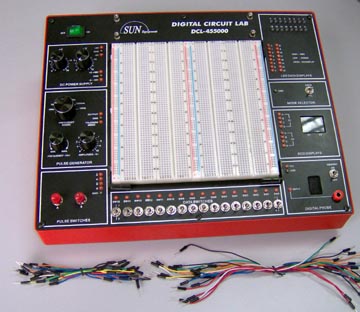
| DCL-455000: Digital Circuits Lab |
Specifications:
1. SOLDERLESS BREADBOARD:
Interconnected nickel plated with a total of 2320 tie points, fits all DIP sizes and components with lead and sold wire AWG #22-30 (0.3 - 0.8mm). It can be changed and replaced fot different applications and can be connected to a demonstration panel.
2. DC POWER SUPPLY
Fixed +5VDC, 1A
Fixed -5VDC, 300mA
Variable 3V ~ 15VDC, 500 mA
Variable -3V ~ -15VDC, 500 mA
3. MODE SELECTION SWITCH:
TTL and CMOS selections
4. TWO DIGITS OF 7-SEGMENT LED DISPLAY
5. PULSE GENERATOR:
Duty Cycle: 50%
Frequency Range: 1HZ ~ 10 Hz/ 10Hz ~ 100Hz/ 100Hz~ 1KHz/ 1KHz~ 10KHz/ 10KHz ~ 100KHz/ 100 KHz ~ 1KHz
Amplitude: 0~10 Vp-p
TTL/ CMOS Output:
TTL: +5V
CMOS: +VDC (depends on the +VDC output)
6. EIGHT BITS LED DISPLAY:
(a) Mode Selector in the "TTL" Position:
|
Logic Level |
Input Level |
Display Light Up |
|
Lo |
< 0.8 ?0.2V |
Green |
|
Hi |
>2.3 ?0.2V |
Red |
|
Open |
0.8 - 2.3 V |
No Display |
(b) Mode Selector in the "CMOS" Position:
|
Logic Level |
Input Level |
Display Light Up |
|
Lo |
< 30% + VDC ?10% |
Green |
|
Hi |
> 70% + VDC ?10% |
Red |
|
Open |
30% - 70% + VDC |
No Display |
7. TWO PULSER SWITCHES:
A, ? B, B(-)
Output Level:
TTL: Hi = 5V, Lo = 0.1V
CMOS: H i= + VDC, Lo = 0V
8. EIGHT DATA SWITCHES:
TTL: Hi = 5V, Lo = 0V
CMOS: H i= + VDC, Lo = 0V
9. DIGITAL PROBE:
(a) Mode Selector in the "TTL" Position:
|
Logic Level |
Input Level |
Display |
|
Lo |
< 0.8 ?0.2V |
L |
|
Hi |
>2.3 ?0.2V |
H |
|
Open |
0.8 - 2.3 V |
O |
|
Transit |
Lo -> Hi |
P |
(b) Mode Selector in the "CMOS" Position:
|
Logic Level |
Input Level |
Display |
|
Lo |
< 30% + VDC ?10% |
L |
|
Hi |
> 70% + VDC ?10% |
H |
|
Open |
30% - 70% + VDC |
O |
|
Transit |
Lo -> Hi |
P |
(c) Memory:
The two points of LED next to the 7 segment LED Display will keep lighting while they are in the "Level Transition" (Lo-> Hi or Hi => Lo)
10. DIMENSIONS: 12.8" (L) X 9.84" (W) X 3.75" (H)
11. WEIGHT: 5.5 lbs
|
|
|
Copyright 1995~2013 Sun Equipment Corporation. All rights reserved Prices and specs are subject to change without notice.
|
Order 1-800-870-1955 |