Curriculum Objectives
* To understand basic theories of analog communication system
* To design and implement analog modulator and demodulator
* To understand the applications of analog modulator and demodulator circuits.
Curriculum Outline
* Design and Implementation of second order active filters and RF oscillators
* Design and implementation of AM/ FM modulation and demodulation
* Design and implementation of DCB-SC and SSB modulator and demodulator
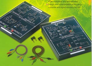
* Design and implementation of TDM and FDM multiplexer and demultiplexer
* Design and implementation of frequency converter and signal recovery circuits.
ACL-10201
Second Order Active Filters
Experiment 1: Second Order Active Low-pass Filter
(Low-pass -3dB Frequency: 1 kHz ~ 3 kHz)
Experiment 2: Second Order Active High-pass Filter
(High-pass -3dB Frequency: 5 kHz ~ 10 kHz)
Experiment 3: Second Order Active Bandpass Filter
(Center Frequency: 10 kHz~ 100 kHz, bandwidth: 6kHz ~ 60kHz)
RF Oscillator Circuits
Experiment 1: Colpitts Oscillator Circuit
(Oscillation Frequency: 1 MHz ~ 9 MHz)
Experiment 2: Hartley Oscillator Circuit
(Oscillation Frequency: 500 kHz~ 1.8 MHz)
Experiment 3: Crystal Oscillator Circuit
(Oscillation Frequency: 500 kHz~ 1.8 MHz)
Experiment 4: Voltage Controlled Oscillator Circuit
(Oscillation Frequency: 3.5 MHz~ 4 MHz)
AM Modulator Design
Experiment 1: Transistor AM Modulator
(Carrier Signal: 1.5kHz~2 kMHz, Audio Signal Frequency: 500 Hz ~ 1kHz)
Experiment 2: MC 1496 AM Modulator
(Carrier Signal: 500 kHz~1 MHz, Audio Signal Frequency: 500 Hz ~ 1kHz)
AM Demodulator Design
Experiment 1: AM Diode Detection Circuit
(Carrier Signal: 300 kHz; Audio Signal Frequency: 500 Hz ~ 2kHz)
Experiment 2: AM Product Detection Circuit
(Carrier Signal: 500 kHz ~ 1MHz; Audio Signal Frequency: 500 Hz ~ 1kHz)
ACL-10203
DSB-SC and SSB Modulator
Experiment 1: DSB-SC Modulator
( Carrier Signal: 100 kHz ~ 500 kHZ, Audio Signal Frequency: 500 Hz ~ 1kHz)
Experiment 2: SSB Modulator
(Carrier Signal: 200 kHz; Audio Signal Frequency: 500 Hz ~ 1kHz)
DSB-SC and SSB Demodulator
Experiment 1: DSB-SC Product Detector
( Carrier Signal: 100 kHz ~ 500 kHZ, Audio Signal Frequency: 500 Hz ~ 1kHz)
Experiment 2: SSB Product Detector
(Carrier Signal: 200 kHz; Audio Signal Frequency: 500 Hz ~ 1kHz)
FM Modulator Circuit Design
Experiment 1: MC4046 FM Circuit
(Carrier Signal: 2.8 MHz; Audio Signal Frequency: 3 kHz ~ 8 kHz)
Experiment 2: LM566 FM Circuit
(Carrier Signal: 20 kHz; Audio Signal Frequency: 500 Hz ~ 700 Hz)
FM Demodulation Circuit Design
Experiment 1: MC4046 FM Demodulator
( Carrier Signal: 20 kHz; Audio Signal 1kHz)
Experiment 2: LM566 FM Demodulator
(Carrier Signal: 20 kHz; Audio Signal Frequency: 500 Hz ~ 700 Hz)
TDM Multiplexer
Experiment 1: Waveform Generator
(Sine Wave Signal Generator: 13kHz; Triangle Wave Signal Generator:2.3 kHz, Square Wave Signal Generator: 2.3 kHz)
Experiment 2: TDM Multiplexer
(Transmission Channels: 3 Channels, Switching Time: 500 ms ~ 50 ms)
TDM Demultiplexer
Experiment 1: TDM Demultiplexer
(Transmission Channels: 3 Channels, Switching Time: 500 ms ~ 50 ms)
FDM Multiplexer
Experiment 1: FDM Signal Generator
(Carrier Signal: 500 kHz ~ 1.5 MHz; Audio Signal frequency: 500 Hz ~ 1.5 kHz)
Experiment 2: DSB-SC Modulated Signal Generator
(Carrier Signal 500 kHz ~ 1.5 MHz, Audio Signal: 500 Hz ~ 1.5 kHz)
Experiment 3: FDM Multiplexer
(Modulation Type: DSB-SC Signal, Transmission Bandwidth: 2 MHz)
FDM Demultiplexer
Experiment 1: FDM Demultiplexer
(Modulation Type: DSB-SC Signal, Demultiplexing Type: Product Demultiplexer)
Analog to Digital Converter Circuit Design
Experiment 1: ADC 0804 Analog-to-digital Converter Circuit
( Resolution: 8 bits; Analog Input Voltage: 0V ~ 5V)
Experiment 2: ADC 0809 Analog-to-digital Converter Circuit
( Resolution: 8 bits; Analog Input Voltage: 0V ~ 5V; Clock Frequency: 120 kHz)
Digital to Analog Converter Circuit Design
Experiment 1:R-2R Digital-to-analog Converter
( Digital Input: 4 bits; Analog Output Voltage: 0V ~ 5V)
Experiment 2:Unipolar DAC 0800 Digital-to-analog Converter Circuit
( Digital Input: 8 bits; Analog Output Voltage: 0V ~ 5V; Step Value: 0.019V)
Experiment 3: Bipolar DAC 0800 Digital-to-analog Converter Circuit
( Digital Input: 8 bits; Analog Output Voltage: -5V ~ 5V; Step Value: 0.038V)
ACL-10208
Frequency Converter
Experiment 1: Frequency Multiplier
(Carrier Signal: 10 kHz)
Experiment 2: Up/ Down Frequency Converter
(Carrier Signal @Lo port: 100 kHz, Carrier Signal @ RF port: 120kHz)
Signal Recovery
Experiment 1: Carrier Signal Recovery Circuit
(Carrier Signal: 10 kHz)
Experiment 2: Clock Recovery Circuit
(Clock Signal: TTL, Encoded Signal: Manchester, Clock Frequency: 5 kHz~10 kHz)
Optional Equipments
FG-442002: Function Generator and DC Power Supply (optional)
Function Generator:
Two signal output ports
Freq. Range: 10 Hz ~ 100KHz and 100Hz ~ 1 MHz
Waveforms: Sine, Triangle, Square, TTL Pulse
Amplitude: 10 Vpp
Built-in 6-digit frequency counter
Large 0.5" LED display
Overload protection
DC Power Supply:
Triple bipolar voltage output
Constant voltage operation
Low ripple and noise
Oscilloscope (optional)